


There are currently an estimated 4.9 billion embedded systems distributed worldwide. By 2020, that number is expected to have grown to 25 billion. Embedded system scan be found virtually everywhere, ranging from consumer products such as Smart TVs, Blu ray players, fridges, thermostats, smart phones, and many more household devices. They are also ubiquitous in businesses where they are found in alarm systems, climate control systems, and most networking equipment such as routers, managed switches, IP cameras, multi-function printers, etc. Unfortunately, recent events have taught us these devices can also be vulnerable to malware and hackers. Therefore, it is highly likely that one of these devices may become a key source of evidence in an incident investigation. This paper introduces the reader to embedded systems technology. Using a Blu ray player embedded system as an example, it demonstrates the process to connect to and then access data through the serial console to collect evidence from an embedded system nonvolatile memory.
1. Introduction
In a world where the Internet of Things is becoming a thing, embedded devices have become ubiquitous. In fact, nearly all classes of electronic devices are becoming embedded systems. According to a recent Gartner analysis, there are currently 4.9 billion embedded systems in use worldwide, and the number is expected to grow to 25 billion by 2020 (Gartner, 2014). Embedded devices can be found in a growing number of businesses with industrial grade appliances including routers, switches, IP cameras, alarm systems, lighting and climate controls, multi-function printers, and a rising number of consumer electronic goods such as smart TVs, Blu-ray players, fridges, thermostats, smart phones, etc. Even modern Supervisory Control and Data Acquisition (SCADA) systems are considered embedded systems. In fact, there is an increasing demand for embedded devices with greater computing power, better connectivity, and broader functionality while keeping implementation costs as low as possible. As a result, the vast majority of manufacturers have adopted some form or other of embedded Linux OS because of its relatively low cost, broad community support, and compatibility with an extensive range of hardware.
Most of these embedded devices come with custom-made user interfaces meant to simplify and constrain the end-user/administrator interaction to very specific actions and displays. This is helpful for preventing most accidental or intentional acts that could render the device irrevocably inoperable. But, there is a lot more going on under the hood. Logs are being generated, data is being saved to flash memory, changes are made to the device’s configuration files, and more—a lot of which remains inaccessible using the custom-made interface.
In addition, embedded device security has been improving over these past few years. Not so long ago, it was rare to find an updated embedded system. This resulted in numerous avenues of attack opening up whenever a new vulnerability with Linux was discovered. Now, many devices update themselves automatically while others consistently remind the end user to authorize the update. However, there always remains a window of opportunity open between the time a vulnerability is discovered and the time a patch is engineered into an embedded system then deployed (Barry & Crowley, 2012).
Case in point, in January 2014, a security research company by the name of Proofpoint1 uncovered a botnet composed of more than 100,000 everyday consumer devices, such as home-networking routers, connected multi-media centers, televisions and at least one refrigerator, that had been compromised and used as a platform to distribute phishing and SPAM emails (British Broadcasting Corporation (BBC) 2014).
Therefore, the embedded devices running within an environment usually are limited in functionality and more effort is needed to access and are not infallible. What if the next embedded device malware does something more nefarious than sending SPAM and an analysis of the device is required to assess the impact to the organization? Perhaps there are clues that can be found on the embedded device? Unfortunately, the user interface does not provide the necessary means to easily access these hidden parts. But in most cases, there is another way of getting to this data.
2. Accessing an embedded device via the serial port
2.1. Embedded system primer
Embedded systems are custom purpose computers that are typically designed for one type of application. Design trade-offs are made to accommodate size, power, and application requirements. As a result, embedded computer systems are different, both from one another and from general-purpose computers by the virtue of their design trade- off and the constraints they embody (Barry & Crowley, 2012). But, regardless of these trade-offs, all systems share a common set of core features and capabilities whose understanding unlocks the ability to manipulate and access them in ways that are far beyond the means provided by the device’s standard user interface.
2.1.1. Embedded System anatomy
Unlike a traditional PC that comes equipped with as much functionality and as many expansion ports as possible, an embedded system usually comes with the bare minimum required to carry out its assigned functions. Some embedded systems have a powerful standalone CPU and supporting chipsets to accommodate diverse subcomponents while others use a System-on-Chip (SOC) approach where all subcomponents are directly integrated with the CPU. Regardless of the approach, CPU/chipset combo or SOC, an embedded system, can be expected to be equipped with a number of standard subcomponents. This includes volatile memory, such as SDRAM, where the OS and programs will be run from, non-volatile memory, such NAND Flash memory for data storage, and input/output (IO) controllers to allow the system to interact with its environment. It is virtually impossible nowadays to find an embedded system without serial, USB, and networking (Ethernet and/or Wifi) comptrollers included either on the board or directly integrated into the SOC processor.
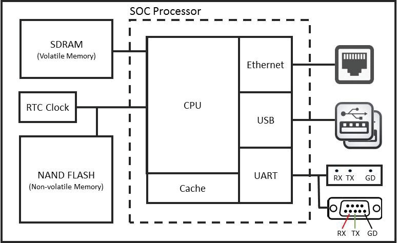
Figure 1: Simple Embedded System Using SOC Processor – (Source: Author)
2.1.2. Universal Asynchronous Receiver/Transmitter UART) controller
Of particular interest for this paper is the serial communication comptroller, also referred to as the Universal Asynchronous Receiver/Transmitter (UART) comptroller. This is one of the most basic components that can be found on an embedded system and uses only 3 wires: Transmit (TX), Receive (RX), and Ground (GND). It is used extensively by system engineers during the development and testing phases . By connecting to this comptroller, it becomes possible to read hardware boot sequence messages, interact with the bootloader, and gain console access once the embedded Linux OS is loaded.
Using one of several communication standards, the UART comptroller is responsible for all the tasks, timing, parity checking, etc. needed for the serial communication to succeed. The most commonly used standard is RS-232, which is also conveniently available on most PCs and laptops. If the incident handler’s computer is not equipped with a serial port, a USB-to-Serial adapter can be easily procured online and configured to work with most Windows and/or Linux platforms as described later in this paper.
Each transmission flowing through the serial comptroller must obey a set speed limit and adhere to specific communication parameters that consists of a start bit, data bits, an optional parity bit and stop bits. To successfully communicate, both the embedded system and the incident handler’s computer bit speed, data length, parity, and stop bits must be set to the same values. Much like a modem, there are many different transmission speeds supported: 300, 600, 1800, 2400, 4800, 7200, 9600, 14400, 19200, 38400, 57600, and 115200 bits per second (bps). However, the most commonly used speeds are 9600 bps, 38400 bps, and 115200 bps. The other most commonly used settings are no parity, 8 data bits, and one stop bit usually written as 8N1 (Barry & Crowley, 2012).
On the incident handler’s computer, a terminal console application is used to communicate through the computer serial port with the embedded system. Because the embedded system will have its serial communication settings pre-configured, the incident handler’s computer terminal console will need to be configured to match the embedded system settings in order to communicate successfully. The easiest way to find out if the embedded system uses the RS-232 standard and what communication settings are pre- configured is to lookup the embedded device specifications online. If it is not clearly stated on the device specification documentation, then looking up the specifications of the SOC processor or chipset used by the embedded device might yield the required information. As a last resort, it is possible to try various configuration settings until the terminal console outputs meaningful text. Configuring the communication protocol through the terminal software is relatively simple and will be explained later in section 2.4.
Finally, the RS-232 specification allows for voltages ranging between 5 and 25 volts (Electronic Industries Alliance (EIA) Standards, 1969). 5 volts is the standard voltage found on computer serial ports. It is also the standard voltage found on the serial connectors of most computing and networking gear equipped with an external serial port. However, some of the more recent embedded systems employ a modified UART comptroller operating at 3.3 volts. Although the RS-232 specification explicitly requires the UART comptroller to be able to work at voltages as high as 25 volts, discussion forums are littered with posts of people having “fried” their embedded device UART comptroller running at 3.3 volts after having connected it directly to a PC serial port running at 5 volts. The obvious solution to avoid such problems is for the incident handler to use a computer equipped with a serial connector with matching voltage. Methods to measure an embedded device’s UART voltage is discussed later in section 2.3.2 while USB-to-Serial adapters able to supply different voltages are shown in section 2.2.1.
2.1.3. Embedded system boot process
When power is applied to an embedded device, the hardware begins its initialization sequence starting with the CPU. The CPU fetches the hardware initialization code, called preloader (or BIOS), from a specific flash storage chip. The preloader is software stored in flash memory that provides a consistent set of OS-agnostic software interfaces that abstract the underlying details of the hardware (Rothman & Zimmer, 2013). The preloader is also responsible for initializing the remainder of the embedded device hardware including volatile memory, also known as RAM, and IO components including the UART, PCI Bus, USB, and SATA comptrollers. Because of its simplicity, UART is most often the first communication port used to communicate debugging information from an embedded device. Finally, the last task of the preloader is to initialize the system storage, identify the boot device, and transfer control to the next agent in the boot process: either the bootloader or the operating system directly (Barry & Crowley, 2012).
The concept of bootloaders is universal to virtually all operating systems, whether a full-fledged PC or the smallest embedded device (Waqas, 2010). The bootloader’s main responsibility is getting the operating system from wherever it is stored, loading it into RAM and launching it. Most bootloaders can support booting from multiple storage locations and some even support loading OSes from the network or external storage temporarily attached to the embedded device. The bootloader will generally output boot diagnostic data to the serial port. It may even be possible for a short period of time to interrupt or at least interact with the bootloader through a terminal console connected to the device serial port. This can be particularly useful to:
- modify the Linux boot arguments;
- instruct the bootloader to load a different OS;
- save the firmware, embedded OS, or file partitions over the network or to a portable device; or,
- replace the existing embedded OS with new one from network or removable media.
However, functionality greatly differs amongst the various bootloaders available and with the exception of modifying the Linux boot arguments, interaction with the bootloader is beyond the scope of this paper.
The Unified Extensible Firmware Interface (UEFI) is a more sophisticated, 2nd generation preloader/BIOS that has become the de-facto firmware for most PCs. It is also starting to make inroads into embedded systems built around Intel SOCs. UEFI brings numerous improvements over the older technology such as only loading an OS with signed code. Bootloader programs that work with preloader/BIOS firmware are incompatible with UEFI. That said, most bootloaders have been ported and now support the more advanced features provided by UEFI. However, for the purpose of this paper, preloader, BIOS, and UEFI can be used interchangeably.
In an effort to reduce costs, heat, and power use, most embedded systems are designed around an ARM SOC instead of using Intel technologies. Until very recently, there was no equivalent to the BIOS for the ARM processor. Each instances of ARM Linux kernel had to be hard coded for the hardware it was meant to execute on (Rothman & Zimmer, 2013). Hence, a number of ARM based embedded systems will be hardcoded to forego the bootloader and will be able to immediately load the OS, while other systems will use a very basic bootloader only responsible for loading and transferring control to the OS. In all cases, the OS kernel will take on the task of initializing the hardware. Newer designs based on the Open Firmware standard incorporate a more advanced preloader and bootloader architecture for the ARM processor that is increasingly capable of abstracting the underlying hardware. From the incident handler’s point of view, being able to determine if a bootloader is present or if the system boots Linux directly is important to assess possible lines of investigations.
2.2. Tools required
2.2.1. Hardware
The list of hardware components required is as follows:
- Incident handler’s computer or laptop;
- USB-to-Serial adapters capable of operating at 3.3v or 5v as required;
- Serial cables and/or jumper wires;
- Solderless header pins (optional);
- Magnifying glass or magnifying glass app on smart phone (optional);
- Soldering iron and solder (optional); and,
- Digital multimeter.
The incident handler’s computer used for accessing the embedded device must be equipped with a USB port. A serial connector would also be convenient to connect to embedded devices with 5 volts serial interfaces but that can also be easily substituted with the appropriate USB-to-Serial adapter. The incident handler must also have root access to be able to install the necessary drivers and applications. For this paper, a VMWare version of Kali was used, allowing for full control of the OS and the ability to plug in the necessary USB-to-Serial adapters.
As explained in section 2.1.2, not all embedded systems have serial connectors operating on 5 volts. Furthermore, if the embedded system offers a 3.3 volts serial connection, instead of using the incident handler’s PC serial connector, a USB-to-Serial adapter based on the PL2303HX2 or similar chip will be necessary to synchronize the voltage with the embedded system. USB-to-Serial adapters supplying various voltage levels, including the more common 3.3 volts and 5 volts varieties, can be found online for less than $10 USD each. For the sake of brevity, all examples discussed in this paper will assume the use of a 3.3 volts USB-to-Serial adapter equipped with female connectors as shown on the left in figure 2 below.
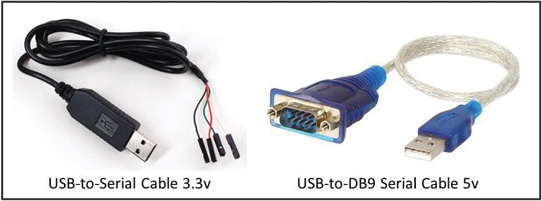
Figure 2: USB-to-Serial Adapters – (Source: Author)
Cables are obviously required to connect the computer and the embedded device together. If the device has an external serial port, then a standard null-modem DB9 serial cable or an RJ-45 to DB9 null-modem serial cable will be required. Null-modem means that the cable will connect the transmit line at one end of the connection to the receive line at the other end and vice versa. However, it is far more likely there will be no connectors present on the embedded device. In this case, it will be necessary to open the embedded device enclosure and scrutinize the Printed Circuit Board (PCB) with a magnifying glass for the transmit (TX), receive (RX), and ground (GND) port headers.
Then, a set of either male-male, female-female, or male-female jumper wires will be required to connect the incident handler’s computer directly to the port headers on the PCB. It is even possible for the circuit board to have holes for the serial connector but no header pins soldered on. In this particular case, solderless header pins can be used to act as an impromptu connector. Finally, if all that is available on the PCB are contact pads, then a soldering iron, solder, and a pair of steady hands will be required to affix jumper wires and run them back to the USB-to-Serial adapter. The process to find the RX/TX/GND port headers is explained in detail in section 2.3
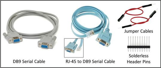
Figure 3: Cables and Wires – (Source: Author)
Finally, a digital multimeter will be necessary to measure the voltage on the embedded system serial connector to prevent damage to the UART comptroller as described in section 2.1.2. The multimeter is also necessary for finding the UART TX, RX and ground (GND) port headers on any embedded system PCB lacking a serial connector. At last, the multimeter will be used to conduct continuity tests to ensure all cables and connections are adequate. A suitable digital multimeter can be found online for less than $10 USD.
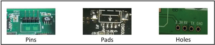
Figure 4: Serial Port Headers – (Source: Author)
2.2.2. Software
This paper was developed using Linux Kali 3.18.0 64-bit. Linux was selected over Microsoft Windows because the PL2303HX drivers came pre-installed and they are loaded automatically when the adapter in plugged-in.minicom is a text-based control and terminal emulation program for Unix-like operating systems capable of serial communication (Lackorzynski & Godisch, n.d.). It is free and can be found on most Linux distributions. minicom interfaces directly with the serial ports available on the computer and enables 2-way communications with the embedded device through the serial cable.
Minicom is relatively easy to operate. The command menu can be summoned at any time using the sequence CTRL-A followed by Z. There are numerous options available. However, the most important are the ability to select the desired serial port and the ability to change the communication parameters (speed, parity, stop bit(s), etc).
Configuration and utilization of minicom will be demonstrated later in section 2.4.
2.3. Connecting the serial port to the incident handler’s computer
The procedure to locate and connect to an embedded device serial port is quite simple. However, precautions must be taken to eliminate the risks of causing irreparable damage to the device or the USB-to-Serial adapter. Furthermore, it is important to take additional precautions, such as using an anti-static mat and bracelet, when manipulating a PCB to prevent damage caused by accidental static electricity discharges.
Under the best of circumstances, the embedded device will be equipped with an external serial connector, and the incident handler will only have to run a null-modem cable between the computer and the device. This is often the case for networking equipment such as enterprise grade routers and switches. However, for other types of embedded devices, it is more likely that the incident handler will need to open the device and search the PCB for the port headers.
2.3.1. Finding the port headers
In most cases, the serial port headers are labeled and easy to recognize. They will take one of three forms: A set of pins, a set of pads or a set of holes as shown in figure 4 below. It is most often composed of four individual port headers and the vast majority of the time, they are arranged in a single row close to each other (Ganssle, et al., 2008). The first header is the ground (GND). The next header is the Transmit (TX) port. The last header is the Receive (RX) port. Note that a fourth header is also usually present. It is the Vcc header and it provides a steady voltage, usually 3.3 or 5 volts. While useful to help identify a set of serial port headers, it will otherwise not be required for the purpose of this paper.
The easiest method to find the serial header ports is to do a quick google search for the embedded device model number and the words “UART” and “Serial”. If the device is widely popular, such as a Kindle Fire3, a Raspberry Pi4, or a NEST thermostat5, it is very likely that someone else has done the research, located the headers; and most importantly, documented the communication parameters and voltage required.
The next best approach is to open the embedded device and conduct a visual search. It is very likely that the words “GND, TX, RX, and 3.3 (or 5v or VCC)” will be printed on the PCB right next or very near their respective headers as shown in figure 4 above.
The location, size, and shape of the header ports will vary from system to system. As a result, some critical thinking and testing may be required. For example, some systems only have the TX and RX headers labeled. In such cases, the USB-to-Serial ground wire can be connected to any shielding or other parts of the PCB identifiable as a ground. And, in some rare instances, the UART port may simply not be labeled at all. Finding the port headers under this circumstance is beyond the scope of this paper. However, help is available online for the interested reader.
2.3.2 Confirming the serial port headers
Regardless of the method used to locate the serial port headers, it is strongly recommended to verify each port header individually using a multimeter to avoid causing irreparable damage to the embedded device or the serial adapter on the incident handler’s computer. The most important characteristic to verify is the voltage between the ground port header and each of the other port headers, none of which should exceed by more than 10% the voltage rated for the serial connector used on the incident handler’s computer.
The ground pin can be easily confirmed by carrying out a continuity test. Simply set the multimeter to the lowest Homs (Ω) setting available. The multimeter readout should be displaying “1”. Touching both ends of the probes together should display “0.01” or a number very close to it. Next, connect one of the probes to the suspected ground port header and connect the other one to any shield casing on the device. Again, the multimeter readout should display “0.01” or a number very close to it if the port header is the ground.
For the remainder of this section, testing will need to be conducted with the device powered on. The next test is for the Vcc pin. Although it will have no further uses after this test, it is important to ascertain the embedded device operating voltage. With the multimeter set to 20 volts – direct current, connect one probe to the ground port header and the other to the suspected Vcc port header. The readout should be a steady 3.3 or 5 volts ±10%.
Next, the TX port header can be tested. For this test, it is best to power off the device and power it back on as the serial port is more likely to be transmitting data via the serial connection during the boot up process. For the purpose of binary serial communication, 1’s are represented as 3.3/5 volts and 0’s as 0 volts Jimb0, 2010). Therefore, the voltage in the TX header should be fluctuating rapidly between 3.3v and 0 volts. Given the speed of transmission, which is at least 300 bits per second and more likely several thousand bits per seconds, the multimeter will quickly resolve to displaying the average: ~1.6/2.5 volts.
The last remaining port header will be the RX port header. Unlike the Vcc and TX port headers, there are no specific voltage levels to anticipate. While it would be logical to assume the voltage on the RX header to be 0 volts, each device tested during the research phase of this paper produced different voltage readings on the RX port header. Therefore, it is not possible to confirm if a port header is the RX port by simply using a multimeter. In the best circumstances, the port headers will be clearly marked. Otherwise, the incident handler will have to rely on the process of elimination to make an educated guess on which header is the RX port. In either case, it is highly unlikely that any damage will result from connecting the wrong port header to the incident handler’s TX port as long as the voltages on both devices match within 10%.
2.3.3. Making the physical connection
When connecting two serial devices together, the transmit (TX) port on the first device must be connected to the receive (RX) port of the second, and vice-versa. This type of connection is known as a null modem (Hallinan, 2010). If both the embedded system and the incident handler’s computer are equipped with external serial connectors, then a null modem cables as shown in figure 3 on page 10 can be used. However, if either or both devices only have port headers located on the PCB, then jumper cables will be required.
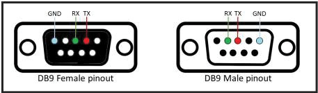
Figure 5: DB 9 Serial Connector Pinout. – (Source: Author)
If the embedded device is equipped with header pins, then a set of three male- female jumper wires can be used to connect to the USB-to-Serial adapter as shown in figure 6. If the device is equipped with header holes, then solderless pins can be used to create a temporary set of pins and the connection can be configured as per the previous example.In cases where the embedded device has header pads, then some soldering work may be required. Soldering is not that difficult and instruction videos abound on YouTube.com. But first, it would be a good idea to check out the blog titled “A solder- free UART connection6”, which offers an imaginative alternative using spare pin headers
In cases where the embedded device has header pads, then some soldering work may be required. Soldering is not that difficult and instruction videos abound on YouTube.com. But first, it would be a good idea to check out the blog titled “A solder- free UART connection6”, which offers an imaginative alternative using spare pin headers and a cloth pin. Regardless of the approach used to attach the jumper wires to the header pads, it is highly recommended to conduct a continuity test between each adjacent jumper wires to ensure that a short was not unintentionally created while securing the jumper wires to the PCB. Also, repeating the validation tests at the other extremity of the jumper wires for the GND and TX ports as described in section 2.3.2 will eliminate the probability of communication failure due to an imperfect connection between the jumper wire and the header pad.
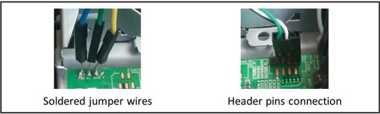
Figure 6: Physical Connections to Serial Port Headers – (Source: Author)
2.4. Configuring the terminal console and connecting to the embedded device
2.4.1. Configuring minicom
Now that the devices are physically connected, it is time to configure minicom to be able to read the data being transmitted by the embedded device. The very first step is to enumerate the serial ports available on the incident handler’s computer using the command dmesg | grep tty. In the example below, we can see the computer has both a standard serial port (ttyS0) and a USB-to-Serial Adapter (ttyUSB0) available.
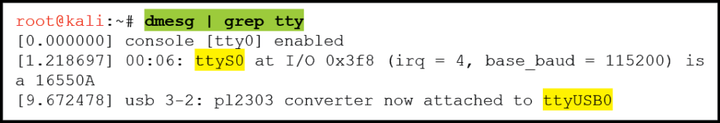
Figure 7: Kali Terminal Window: Command to List Available Serial Connectors – (Source: Author)
Next, we are ready to execute minicom and configure it to use the desired serial port. To do this, enter the command “minicom -s“ in the terminal window to start the application and follow these steps once the minicom application is running:
- Scroll down to the “Serial port setup” sub-menu item and press ENTER;
- When the “Serial port setup” menu is displayed, press B to edit the Serial device;
- Replace the serial device name with the one desired (/dev/ttyS0, /dev/ttyUSB0, etc…); and,
- Turn off all Flow Control features using the letters F and G.
The next step is to configure the communication parameters. Ideally, the parameters will have been discovered while researching the device hardware specifications as suggested in section 2.1.2. Otherwise, try 115,200 bps with 8N1 to begin with. While still in the “Serial port setup window”, press E to access the communication parameter menu. Enter the desired parameters and exit the menus by pressing ENTER until you return to the “configuration menu”. Then, it is highly recommended to save the configuration using the menu item “Save setup as dfl”. This will ensure that any changes made will persist across application restarts and system reboots. Finally, exit the configuration menu and return to the minicom console.
2.4.2. Establishing and troubleshooting the connection
The incident handler’s system is now ready and listening to the selected serial port. Powering up the embedded device will initiate the boot process, and soon after, data should be pushed on the screen in the minicom terminal console. If there is no data, it is likely due to one of the following issues listed in decreasing order of likelihood:
Table 1. Serial connection troubleshooting scenarios.
| Problem | Troubleshooting Approach |
|---|---|
| Wrong serial device (ttyS0, ttyUSB0) selected in minicom |
|
| Incorrect communication parameters |
|
| Faulty wire or connection between the devices (i.e. cold solder) |
|
| Port headers on embedded device not a serial connection |
|
| Serial port on embedded device disabled at the hardware level (practically unheard of as of this writing) |
|
If there is data displayed but it is garbled, then the embedded device is transmitting data that is being successfully received by the incident handler’s computer.
2.4.3. Communication parameters discovery
If incorrect communication parameters is the suspected cause as to why minicom is not receiving the embedded device data output, then the only definitive way to find the correct parameters is to try each of them one after the other until meaningful data appears or all possible permutations have been exhausted. Although this will be a time consuming task, it is possible to increase the odds of finding the correct communication parameters quickly by following a few simple guidelines.
First of all, always start by using “8N1” for the data length, parity bits and stop bits parameters. Only change one of these at the time and only after having exhausted all possible speeds first. Second, begin with 115200 bps and then try 9600 bps and 38400 bps as these are by far the most common speed parameters. If unsuccessful, try all other possible speed starting with the fastest: 57600, 19200, 14400, 7200, 4800, 2400, 1800, 600, and finally 300 bps.
Also, it is best to power off the embedded device between each attempt as it is much more likely to transmit large bursts of data while it goes through its boot-up sequence. Finally, it is best to exit minicom after each attempt and start is back up with the command: minicom –s. This will bring up the configuration menu and allow immediate access the “Serial port setup” sub-menu to alter the communication parameters following the steps described earlier in section 2.4.1.
2.5. Terminal console interaction
Eventually, the embedded device will boot and the forensic analyst’s computer will begin receiving data that it will display on the minicom terminal console. This is where a creative and resourceful incident handler will shine. Although there will be similarities between embedded systems, not all systems will immediately provide a terminal console with root access. Some research and analysis of the embedded device data output, along with a fair amount of trial and error, will likely be required to coax the device into relinquishing its secrets.
At this point, it is best to power off the embedded device, record the communication parameters and exit minicom. During the boot up process, a lot of information will quickly scroll through the terminal console; too much data in fact for anyone to comprehend in a single passing glance. To ensure that no invaluable piece of information goes unnoticed, it is best to restart minicom with the command line switch “- C” followed by a file name. This will ensure that all input and output are immediately saved to file for later analysis.
For the purpose of this paper, a refurbished Samsung Blu-ray Player, model BD- F5700, was procured online for $40 USD and used as the test system. All examples are drawn from the capture of this Blu-ray player boot-up output and responses to commands entered from the incident handler’s computer.
2.5.1. Initial data analysis
Once minicom is running and is adequately configured to accept incoming data, it is time to turn on the embedded device. It will initialize and begin the boot process as explained earlier in section 2.1.3. After a quick pre-boot hardware initialization, the bootloader is loaded into memory and shortly after, the embedded Linux OS begins loading. This is evident by the data strings typical of most of Linux’s boot sequence screens. The data will continue flowing for up to a minute. But eventually, it will either stop or as is the case with the test system, the same five lines will repeat at regular intervals. This is a sure sign that the boot cycle has completed, and it is now time to dive into the capture file to tease out valuable nuggets of information. Below is a sample output of the capture file from the test system. The notation “…” represents one or more lines of data that have been removed to declutter the example.
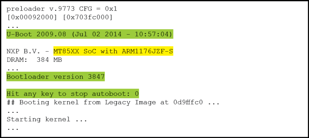
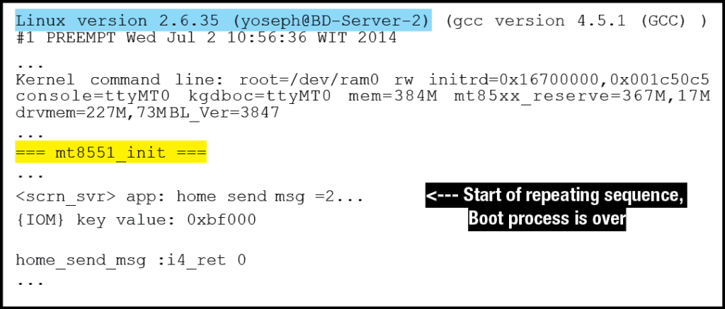
Figure 9: Test System Boot Process Output Summary – (Source: Author)
By looking at this output, it is immediately evident that there are key pieces of information displayed. First of all, the SoC Model number and ARM processor model number are clearly noticeable: “MT85XX SoC with ARM1176JZF-S”. A quick google search reveals that the SoC is manufactured by MediaTek7, and the ARM processor technical reference manual8 is available online. These two sources of information can reveal much regarding the internal workings of the embedded system, including which distributions of Linux are compatible. Looking further down in the output, the exact model number of the SoC is revealed: “mt8551_init”. This information is invaluable to understand the various subcomponents that may be accessible.
The test system also uses the “U-Boot 2009.08” bootloader. Furthermore, it appears that it is possible to stop the bootloader before the OS is loaded into memory and executed (“Hit any key to stop autoboot: 0”). This is obviously a very promising opportunity as it may allow the incident handler to interact with the system before the OS is booted. This particular line of investigation will be explored further in the next section.
Finally, the Linux version is displayed as the OS begins its boot process. The Kernel command line is also displayed, hinting that it may be possible to alter it from the bootloader menu. This possibility will be discussed in the next section. The OS Boot process and terminal console interaction with the OS will be discussed in further detail in section 2.5.3.
2.5.2. Bootloader analysis
It is now time to take a closer look at the bootloader output. As noted in the previous section, the test system bootloader is U-Boot 2009.08 version 3847. Das U- Boot, as it is officially named, is a very versatile bootloader distributed under an open source license and that has become very popular in the embedded Linux community (Hallinan, 2010). Das U-Boot has a very well documented online presence9, and a wise incident handler will quickly review the online documentation to get a sense of U-Boot’s capabilities. Of particular note is U-Boot’s ability to initialize and use the Ethernet port for IPv4 communications. U-Boot is also able to read and write to a USB drive.
Armed with some knowledge regarding the bootloader, it is time to reboot the embedded device. But this time, the incident handler should hit the “ENTER” key repetitively in an attempt to halt the bootloader before it starts loading the OS. This may take a few tries to succeed. The resulting output will look something like this:
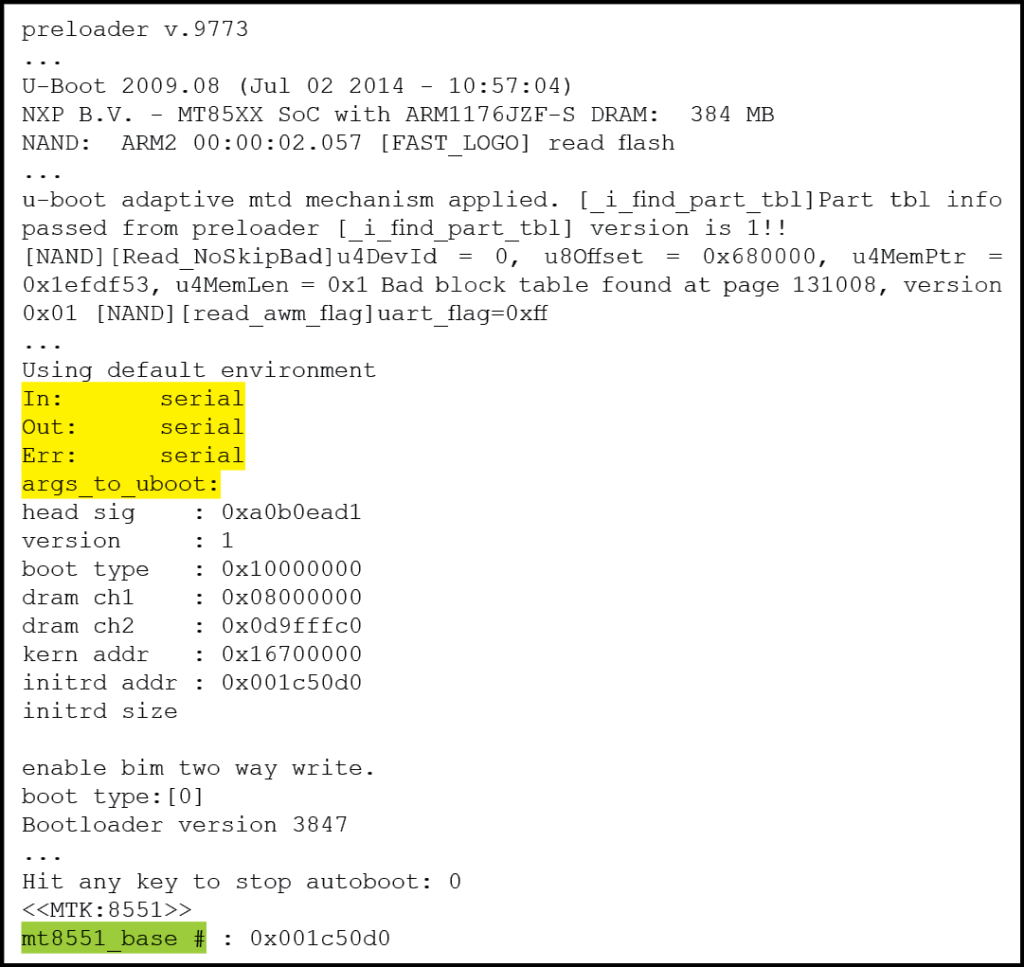
Figure 10: Interrupted U-Boot Sequence Leading to Bootloader Console Prompt – (Source: Author)
The prompt “mt8551_base #” is the indicator that U-boot autoboot has been interrupted and it is now possible to interact through the terminal console with the bootloader. There are several important pieces of information displayed, including the memory address of the embedded Linux OS and the fact that both normal and error output is being sent to the serial console. Entering the command “help” will display a list of commands available to the incident handler.
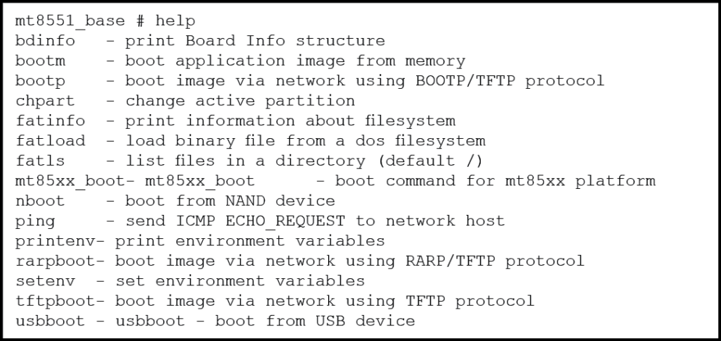
Figure 11: Sample output from “help” command – (Source: Author)
The actual output contains far more commands. However, this paper will quickly highlight only a few of the most important ones. First of all, U-Boot provides several mechanisms to load and execute a Linux OS image from a number of sources including the NAND non-volatile memory, a USB thumb drive, and even across the network. This particular capability could be invaluable if a forensic investigator would wish to access the NAND memory using a custom built embedded Linux OS and then subsequently load the resident OS as a read-only partition for analysis. Other alternatives can include uploading the embedded Linux OS to another location for analysis. This can even be used to replace the existing embedded OS with a different or modified OS.
The bootloader also provides commands to display more valuable information about the embedded Linux OS. For example, the command “bdinfo” will display the boot parameters to be used as well as the device assigned IP address. Whereas the commands “printenv” and “setenv” can be used to view and modify the embedded OS boot arguments.
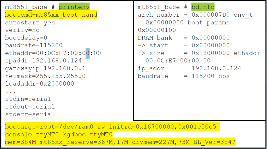
Figure 12: U-Boot “printenv” and “bdinfo” outputs – (Source: Author)
In this particular case, the boot command “mt85xx_boot nand” is easily identified. As a result, it is possible to modify the Linux boot arguments to alter the behavior of the Embedded Linux at boot and then initiate the boot sequence. U-Boot’s capability to easily define, store, and use environment variables makes it a very powerful tool in this area (Schocher , 2011).
This is but a quick overview of what can be done to the test system through the U- Boot console. An entire Gold paper could be written on the ways with which an incident handler could interact with an embedded system using only a bootloader such as U-Boot.
2.5.3. Embedded Linux OS Analysis
Continuing on with the boot sequence, the OS begins to send line after line to the minicom terminal console. This is where a good comprehension of the Linux environment will help the incident handler pick out invaluable data.
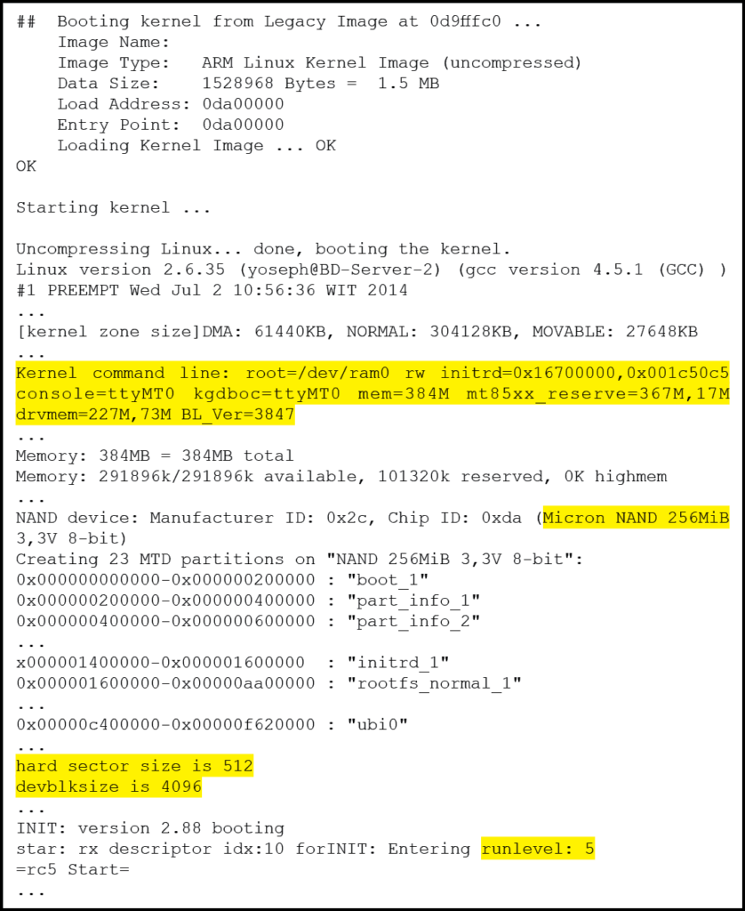
Figure 13: Embedded Linux boot sequence summary – (Source: Author)
First of all, the output displays the kernel command line arguments used. It is particularly useful if the U-Boot “setenv” command was used as described in the previous section to verify that the modified arguments were successfully passed to the OS. Afterward, the OS begins initializing the non-volatile memory and creates “MTD” partitions. The Memory Technology Device (MTD) subsystem for Linux provides access to non-volatile memory storage, typically Flash devices Woodhouse, n.d.). MTD provides the mechanisms for putting fully functional file systems into Flash, which can be read from as well as written to. In addition to indicating the various partitions loaded, this data output also provides mapping to the flash memory address, in effect providing the information necessary to mount these partitions from an OS of the incident handler’s choice as suggested in the previous section.
Finally, the output reveals the OS is entering “runlevel 5”. This is a standard runlevel of a Linux system and by the looks of the follow-on output, it starts the initialization of the test system’s multimedia functionality as well as the on-screen display user interface. This generates more output to the terminal console, which also yields interesting information.
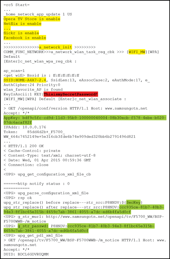
Figure 14: Sample Embedded Linux runlevel 5 console output – (Source: Author)
Of particular interest is the fact that there are 13 applications installed and running. This includes the likes of Netflix, Pandora and Twitter. Any one of which could be a likely vector of infection if the incident handler is investigating the suspected presence of malware. Even more interesting is the fact that the output lists all previously associated wireless access point including the password keys in the clear! Finally, the output begins displaying HTTP traffic with Samsung servers for the purpose of verifying if the firmware is up to date. This appears to require the use of password strings that are again, displayed in the clear. This is interesting because an attacker, if successful with DNS redirection, may be able to replace the embedded device firmware with code of his choosing. This is definitively something the incident handler will want to investigate. Or use himself as an alternate method to inject a firmware of his own.
At some point, the outpouring of data to the terminal console will stop. In many instances, this is where the incident handler finds himself face to face with a Linux shell with root privileges. If this is the case, then he can immediately begin gathering information in the same way he would with any Linux PC. However, as is the case with the current test system, the developers may have programmed in a custom shell to facilitate their needs but also constrains access to some degree. In such cases, the incident handler will have to experiment and see what can be done to elevate his access privileges. Or at least, he would have to collect the information he needs through the custom shell. With the test system, it was possible to invoke a password prompt by sending a CTRL-C command to the system. Simply pressing ENTER returned what appeared to be a list of available commands with a short description.

Figure 15: Embedded Linux custom shell sample – (Source: Author)
It may be possible to get past the password prompt though simple password guessing. Also, a dictionary attack against the password prompt using minicom’s “runscript” script interpreter could be attempted. On the other hand, the commands available through the custom shell may be able to yield most if not all of the information sought by the incident handler. The best approach to investigate such a custom shell is to build a mind map as shown in Appendix A. Then, the incident handler could develop a meticulous plan to investigate the most promising commands.
A thorough analysis of the test system custom shell is beyond the scope of this paper. However, two lines of investigations will be briefly discussed to demonstrate the potential of this approach. First, a close look at the “ave_tcp” sub-command reveals numerous networking tools. This includes tools to display the device IP address dhcpc_get_info ip_info. It also includes tools to resolve IPs and ping hosts on the network hostname hn, dns_lookup dns_lk, ping p, pinghostbyname p_host. And most interestingly, it also provides the mean of enabling a telnet daemon on the embedded device using the command invoke_telnetd td). Having executed this command, the test system indeed had a telnet daemon listening and it was possible to connect to it from the incident handler PC using PuTTY. Unfortunately, the console demanded a login name and password before allowing any further access.
The custom shell also provided a very elaborate set of file management features including the ability to format a partition, mount and unmount partitions, copy and compare files, and much more. But perhaps the most interesting features are the abilities to list directory contents and read files. These two commands alone enable the incident handler to conduct a complete reconnaissance of the file system looking for data of interest. Figure 16 and figure 17 provides directory listings of some of the more interesting folders.
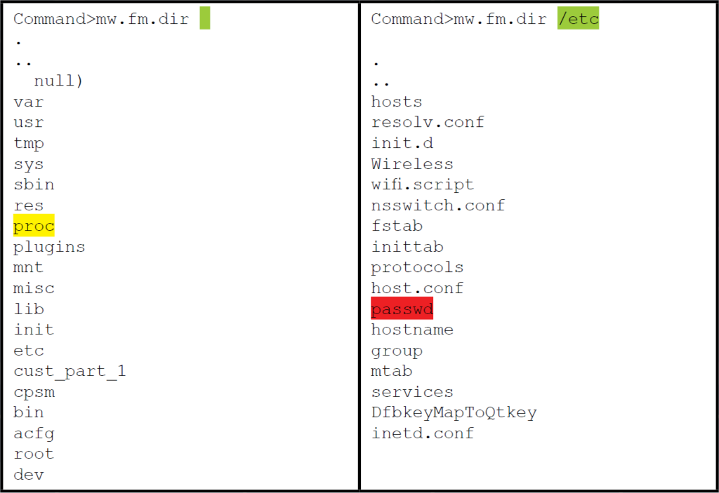
Figure 16: Directory listings using the command “dir” – (Source: Author)
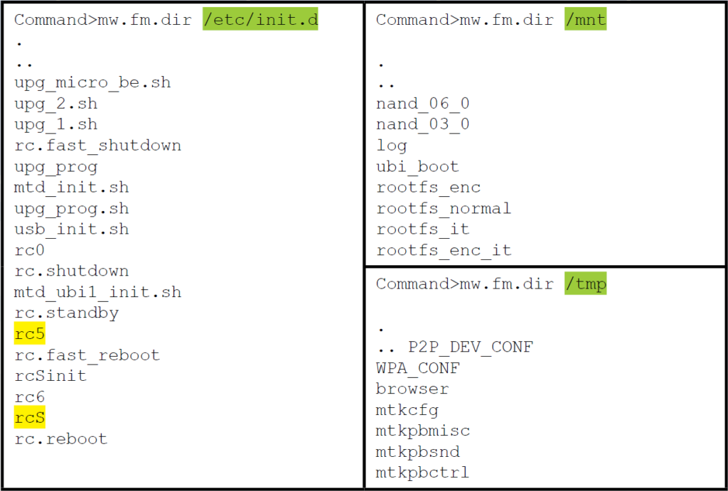
Figure 17: More directory listings using the command “dir” – (Source: Author)
It is possible to gather more information on the system and the OS using the “read” command to access the various data elements in the “/proc” directory such as cpuinfo, version and mounts. However, the output is in hexadecimal. Therefore, some conversion will be required to read the output. Thankfully, this can be easily remedied using RapidTables.com Hex to ASCII converter10. It is also possible to read and even modify runlevel scripts. Although there is no built-in text editor, it is still possible to edit or even replace the script using the “cp” command to overwrite the file. Finally, Figure 17 shows that the file “/etc/passwd” is listed but unfortunately, the file “/etc/shadow” is missing. This could be a sign that the custom console is running with restricted privileges. Nevertheless, it is worthwhile to look at the “/etc/passwd” file to see what user accounts are available. Figure 18 below demonstrates the command to display the “/etc/passwd” file and the resulting output conversion into ASCII.
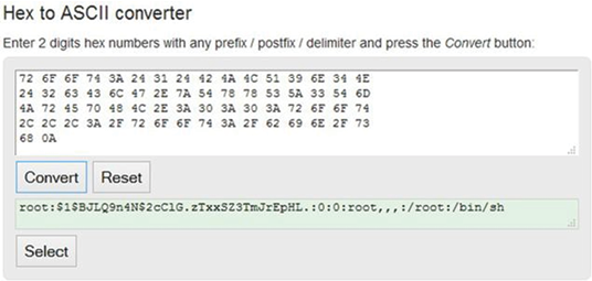
Figure 18: /etc/passwd read from custom shell and converted into ASCII – (Source: Author)
The result is a pleasant surprise. The file not only contains a single username. Which suggests the custom shell is indeed running with root privileges. But it also contains the hashed password. Yet another avenue of analysis where the incident handler may choose to run a password cracking tool such as hashcat11 to conduct a dictionary attack or bruteforce the password and gain root console access via the “CTRL-C” input directly at the serial console or thought the telnet console discovered a few paragraphs earlier.
3. Conclusion
With the rapidly growing number of embedded devices found virtually everywhere, and recent indications of such devices having been compromised and some even used in botnets, it is only a matter of time before one of them becomes a key link in your incident investigation. However, an embedded device does not need to be thought of as an insurmountable obstacle from which evidence collection is impossible. With a basic appreciation of embedded systems architecture, a decent understanding of the boot process, and a good grasp of Linux, it is possible to access key files located on embedded systems that can potentially hold invaluable evidence for the investigation.
The serial port is one of the oldest technologies available in embedded systems today. Because of its simplicity and ease of use, it is the interface of choice for system developers, allowing them to easily read messages from and interact with the system during boot and normal operations. As a result, they can also be used by an incident handler to access the inner workings of an embedded system. But, serial ports have gone through some improvements over the years to better suit the needs of embedded systems. Therefore, not only is it important to correctly identify the serial port headers on a PCB, but the incident handler must also be able to determine the voltage used to avoid damaging the embedded device or the PC used to connect to it.
Once physically connected, it becomes possible to interact with the system bootloader to image, copy, replace, or alter the embedded Linux OS and/or non-volatile file storage. At the very least, access to the bootloader permits the alteration of the boot parameters in a manner favorable to the incident handler. Also, many embedded devices serial console will immediately present a root shell. Others will offer a shell with limited capabilities. However, as demonstrated in this paper, even with a limited shell it is still possible to access the most critical areas of the file systems up to and including the “passwd” file.
In conclusion, this research project demonstrates an overview of the potential actions an incident handler may take when investigating an embedded system OS. In practice, the extent of the investigation is really limited by the breath of the handler’s experience and his imagination. All it really takes to succeed is a determined incident handler with a sound understanding of the technologies involved, patience, an ability to think critically, and a structured approach for the door to the inner workings of embedded systems to be opened.
References
- Barry,P., & Crowley, P. (2012). Modern’Embedded’Computing:’Designing’Connected,’ Pervasive,’Media9Rich’Systems. Waltham, Mass: Morgan Kaufmann.
- British Broadcasting Corporation BBC. (2014), January 17 . Fridge’sends’spam’ emails’as’attack’hits’smart’gadgets. Retrieved from bbc.com: http://www.bbc.com/news/technologyL25780908
- Electronic Industries Alliance EIA Standards. (1969) . RS232’Specifications’and’ standard. Retrieved from lammertbies.nl: http://www.lammertbies.nl/comm/info/RSL232_specs.html
- Ganssle J., Noergaard, T., Eady, F., Edwards, L., katz, D., Gentile, R., . . . Huddleston, C. (2008), March 26 . Embedded’Hardware’Know’it’all. Elsevier: Newnes. Retrieved from BeyoundLogic.com
- Gartner. (2014), November 11 . Gartner Says 4.9 Billion Connected “Things” Will Be in Use in 2015. Gartner’Newsroom. Retrieved March 17, 2015, from http://www.gartner.com/newsroom/id/2905717
- Hallinan, C. (2010) . Embedded’Linux’Primer:’A’Practical’Real9World’Approach. Crawfordsville, Indiana: Prentice Hall.
- Jimb0. (2010), November 23 . RS9232’vs.’TTL’Serial’Communication. Retrieved March 19, 2015, from sparkfun.com: https://www.sparkfun.com/tutorials/215
- Lackorzynski, A., & Godisch, M. n.d. . Project’Info. Retrieved March 18, 2015, from Minicom Project Page: https://alioth.debian.org/projects/minicom/
- Rothman , M., & Zimmer, V. (2013), May 29 . Using’UEFI’in’embedded’and’mobile’ devices. Retrieved March 24, 2015, from LinuxGizmos.com: http://linuxgizmos.com/usingLuefiLinLembeddedLandLmobileLdevices/
- Schocher , H. (2011), October 19 . 7.4.’Boot’Arguments’Unleashed. Retrieved March 24 2015 from DENX ULBoot and Linux Guide DULG : http://www.denx.de/wiki/view/DULG/LinuxBootArgs
- Waqas, A. (2010), October 28 . What’Is’Bootloader’And’How’To’Unlock’Bootloader’On’ Android’Phones'[Complete’Guide]. Retrieved 03 27, 2015, from addictivetips.com: http://www.addictivetips.com/mobile/whatLisLnlockLbootloaderLonLandroidLphonesLcompleteL guide/
- Woodhouse, D. n.d. . General’MTD’documentation. Retrieved March 31, 2015, from Memory Technology Device HTD Developers page: http://www.linuxL mtd.infradead.org/doc/general.html